The Four Foot Loop Antenna
Materials
To construct the 4 foot loop, it is necessary to procure the following material:
- Two 8 foot lengths of 1 by 2 lumber (the actual size of 1 by 2 lumber is 11/16 by 1 3/8 inches).
- 150 feet of #20 guage solid wire. Probably the cheapest source is thermostat
or doorbell wire, which comes as insulated twisted pair. Simply measure the length of both of the
wires, and then take one conductor of the two for the loop. The other conductor can then be used as the
secondary wire, or for other purposes. Another source of wire is discarded telephone or network cable – simply
splice sections together to make the desired length. These types of wire, however, will give poor results –
particularly at the high end of the band. Multi-stranded antenna wire is better.
- A 9.6 to 365 pF tuning capacitor – the large set of plates in a 2 section tuning capacitor salvaged from a junk radio.
- A terminal block, or some other technique for making three connections.
- 8 wood screws, nails, etc.
Construction
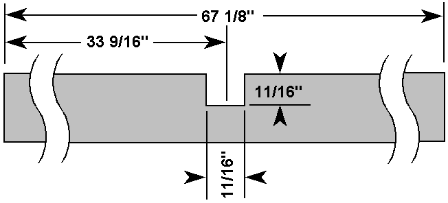
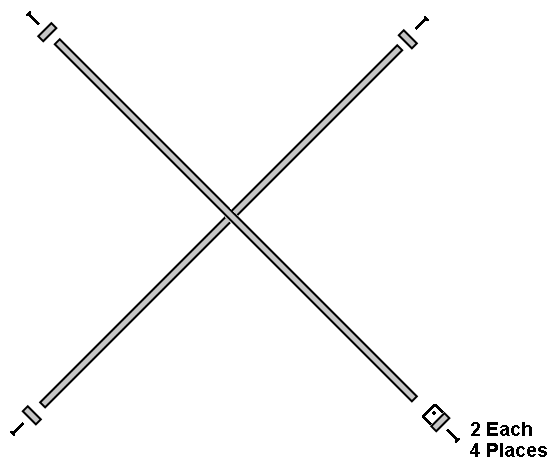
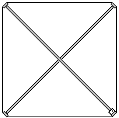
- Cut two 67 1/8 inch lengths of 1 by 2. These are the braces. Make a notch 11/16 inch wide and 11/16 deep in the exact center of each
of these braces.
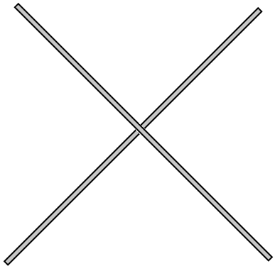
- Make an “X” from the two braces by fastening them together at the notches. Make sure the boards fit together flush, and the two braces
form a 90 degree angle. They can be secured with wood glue, or with a screw if the loop must be disassembled.
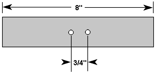
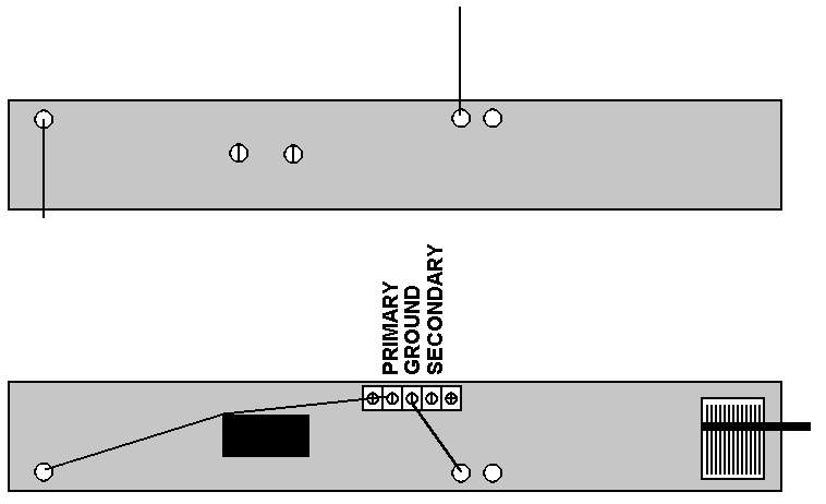
- Using the scrap pieces of 1 by 2, make 3 eight inch
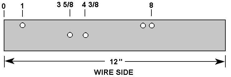
blocks of wood, and one 12 inch block of wood. The 12 inch block of wood will be the tuning block and wire support, the
other three will be wire support.
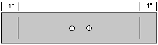
- In the middle of the 3 eight inch blocks, drill two holes 1/8 inch holes spaced ľ inch apart for wood screws. Countersink the holes so
the screws will not interfere with the wire.
- Prepare the turning block as shown below.
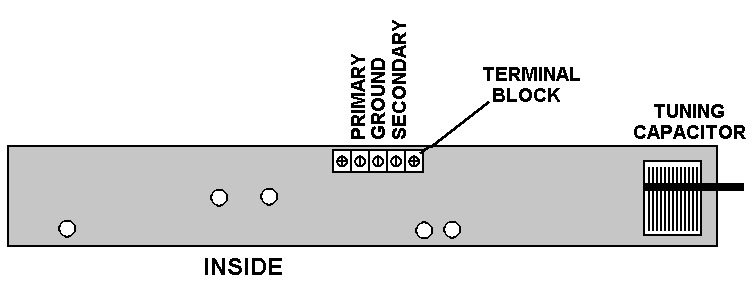
- Attach the terminal block with two wood screws. Attach the tuning capacitor to the board with screws, adhesive, or double backed foam
tape. If the tuning capacitor has to be remotely located because the loop is installed outdoors, put it in a weatherproof outdoor
enclosure. The tuning capacitor can be coupled to a remotely controlled stepper motor to achieve remote tuning.
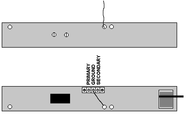
- Attach the three wire supports and one tuning / wire support to the ends of the “X” formed by the crossbraces. It may be necessary to
pre-drill the ends of the braces, as the wood may tend to split. Wood glue may also help.
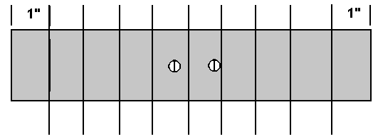
- Make a mark one inch from each end of the eight inch support blocks.
- Carefully route one end of the wire through the second hole from the tuning capacitor on the tuning block. Attach the end to the ground
screw on the terminal block.
- Carefully wind 9 turns of wire around the outside of the loop. It will be quite large and unwieldy, it may be easier to place the loop
horizontally on the floor and go around the loop with the spool. Keep the wire taught!
- At the end of 9 turns, route the other end free end of the wire through the end hole in the tuning block, and attach to the primary
screw on the terminal block.
 NOTE: Intermediate windings not shown for clarity.
- Space out the 9 turns of the winding evenly between the two marks on each support, or between the two wires on the tuning block.
- Wind one turn of wire from the ground terminal screw, around the supports, to the secondary terminal screw.
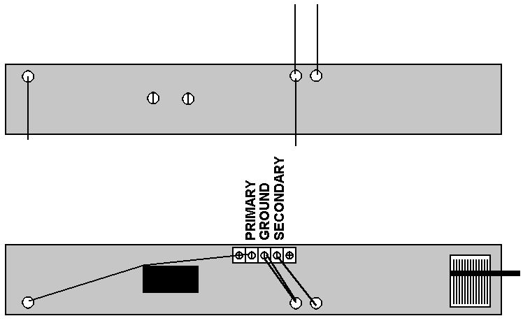
- Connect the ground of the tuning capacitor to the ground screw of the terminal block. Connect the other terminal of the tuning
capacitor to the primary screw of the terminal block.
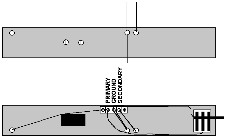
- Connect the ground terminal screw on the terminal block to the ground of the receiver. Connect the secondary screw on the terminal
block to the antenna input of the receiver. Use coax or twisted pair to connect to the receiver.
If the receiver has a ferrite bar antenna, there are two methods of coupling. One is to wrap a few turns of wire around the ferrite bar
at the end opposite the existing windings, and couple those windings to the coax.
Another method is to replace the ferrite bar with the loop. The tuning capacitor would not be used in this case. The ferrite bar in
the radio would be removed, and the primary wired across the tuning capacitor in the radio. The secondary of the loop would then be
connected to the secondary connection in the receiver (where the end wire from the small portion of the winding on the ferrite loop went).
Some receivers do not have common returns for the two windings – in that can the designer needs to connect the proper grounds to their
locations in the receiver.
Test Results
The author’s Dallas / Fort Worth “metroplex” location made testing impossible due to overloading and interference from local stations.
A remote listening location at 33.9N, 101.9W was selected near (but not at) the antenna facility of Texas Tech University in Lubbock. This
site was also selected for high ground conductivity, between 15 and 30 millimhos / m.
Three portable receivers were selected to minimize noise conducted over power lines (notoriously bad at the reception site). These
receivers were a GE 7-2887A (AKA “Superadio 3”), an Optimus 12-603, and an Optimus 12-732. These receivers range from very good to modest.
Tests were conducted using only the receiver’s internal ferrite bar antenna, a Terk “AM Advantage” 9 inch loop antenna, and the loop
described in Appendix A. The Terk AM advantage does not have a frequency range to 1700 kHz. It tops out at 1600 kHz – the old limit of
the AM band. Therefore, it was not capable of tuning one of the test stations.
Tests were conducted in the middle of daylight hours only – no medium wave booster is needed at night in the continental United States.
The test focused on reception of Dallas / Ft. Worth area stations from Lubbock, TX; however, stations were added from different areas as
appropriate. These stations are listed in Appendix B. The most distant stations were characterized by deep fades with periods of an hour
or more, so not all were simultaneously logged. The strength of the distant stations at their peak was enough that the author believes
even more distant stations could also be logged. Stations were logged that do not appear here that were even more distant – however time
prevented positive identification. There was not much point, since it would only serve to further validate the best combination of loop
and receiver, which was the Superadio 3 and the five foot loop, as expected.
The standards of reception below are somewhat subjective, but it is possible to apply standards consistently in a single test session.
The author used the following signal categories:
- No signal
- Carrier only - generated a 10 kHz tone with an adjacent
station
- Slight signal – audio modulation can be heard, but no
intelligible words can be made out
- Unlistenable - intelligible audio can be heard, but there is
so much static and interference that prolonged listening would produce ear
fatigue
- Listenable – the audio is sufficiently good to be listened to
without ear fatigue
- Good Signal – audio is almost clear, but contains artifacts of
10 kHz tones from adjacent stations, bleed over from modulation on nearby
stations, slight residual static
- Clear – no audible interference
As expected, reception using the internal antennas yielded badly degraded and almost unlistenable audio on all but the GE superadio III:
| Frequency |
Call |
12-732 |
12-603 |
7-2887A |
| 540 |
KDFT |
0 |
0 |
0 |
| 610 |
KSVA |
0 |
1 |
2 |
| 620 |
KMKI |
3 |
4 |
5 |
| 640 |
WWLS |
3 |
3 |
4 |
| 650 |
WSM |
0 |
0 |
0 |
| 660 |
KSKY |
3 |
3 |
4 |
| 780 |
WBBM |
0 |
0 |
0 |
| 810 |
WHB |
0 |
0 |
0 |
| 820 |
WBAP |
3 |
4 |
5 |
| 830 |
WCCO |
0 |
0 |
0 |
| 850 |
KOA |
0 |
0 |
0 |
| 870 |
WWL |
0 |
0 |
0 |
| 880 |
KRVN |
0 |
0 |
0 |
| 1700 |
KTBK |
0 |
0 |
0 |
The Terk AM advantage antenna is an unamplified 9 inch loop antenna. The 12-732 receiver does not have an external AM antenna input.
It is merely brought close to the loop windings to inductively couple signal into the internal ferrite loop. It yields some improvement,
but not a lot:
| Frequency |
Call |
12-732 |
12-603 |
7-2887A |
| 540 |
KDFT |
0 |
0 |
0 |
| 610 |
KSVA |
1 |
3 |
3 |
| 620 |
KMKI |
4 |
5 |
5 |
| 640 |
WWLS |
3 |
4 |
5 |
| 650 |
WSM |
0 |
0 |
0 |
| 660 |
KSKY |
3 |
4 |
5 |
| 780 |
WBBM |
0 |
0 |
0 |
| 810 |
WHB |
0 |
0 |
0 |
| 820 |
WBAP |
4 |
5 |
6 |
| 830 |
WCCO |
0 |
0 |
0 |
| 850 |
KOA |
1 |
1 |
2 |
| 870 |
WWL |
0 |
0 |
0 |
| 880 |
KRVN |
0 |
0 |
2 |
| 1700 |
KTBK |
0 |
0 |
0 |
The 4 foot loop yielded dramatic improvement:
| Frequency |
Call |
12-732 |
12-603 |
7-2887A |
| 540 |
KDFT |
3 |
5 |
6 |
| 610 |
KSVA |
0 |
1 |
2 |
| 620 |
KMKI |
6 |
6 |
6 |
| 640 |
WWLS |
6 |
6 |
7 |
| 650 |
WSM |
5 |
5 |
6 |
| 660 |
KSKY |
4 |
4 |
5 |
| 780 |
WBBM |
0 |
0 |
5 |
| 810 |
WHB |
2 |
3 |
4 |
| 820 |
WBAP |
5 |
5 |
6 |
| 830 |
WCCO |
2 |
3 |
3 |
| 850 |
KOA |
3 |
3 |
4 |
| 870 |
WWL |
4 |
5 |
5 |
| 880 |
KRVN |
2 |
2 |
3 |
| 1700 |
KTBK |
0 |
2 |
4 |
The large loop allows many distant stations to be heard on even a modest receiver. As expected, receivers have personalities, related
to the number of IF stages, the presence or absence of a tuned RF stage, and particularly the AGC characteristics. A good example is the
reception of 780 on the 7-2887A (Superadio 3). The other two receivers are manufactured by Radio Shack, and therefore have some
selectivity and AGC characteristics in common. 780 kHz was unreceivable on the Optimus receivers at the test location due to the presence
of a local station on 790 kHz. When the Radio Shack receivers are tuned, strong local stations have a strong presence even 30 to 40 kHz
away from the center frequency, and are much louder in volume. In spite of this, the 12-603 appears to be more sensitive on a few
stations. It also allowed reception of 620 kHz in the “wide” position, providing high frequency response without a large increase in
noise. When the “wide” position was attempted with the Superadio 3 on 620 kHz, the volume decreases markedly. The “wide” position may
have more bandwidth on the Superadio 3 than it does on the 12-603. The reception of KMKI would have rated 7 on all three receivers, had it
not been for a strong source of local noise. Volume on the station increased dramatically as the loop was tuned to 620 kHz.
Stereo reception was not attempted on the three receivers,
because they did not contain an AM stereo conversion circuit. In practice, however, the better the signal
quality, the better the chance of satisfactory stereo reception.
Tru-isms and Other Observations
If there was a single result of this test, it was to confirm
certain facts that are self-apparent, but seldom questioned. These facts are listed below:
- Better quality receivers have the capability of more distant reception than modest receivers.
- Receivers with tuned RF stages are more sensitive. Two of the receivers used in this test have tuned rf stages – the 7-2887A (Superadio
3), and the 12-603. This is not the complete story, however, as the 12-603 had a lot more in common with the 12-732 than it did with the
7-2887A.
- Larger antennas receive more stations than small ones. The Terk AM advantage 9 inch loop helped the modest 12-732 and 12-603 receivers
far more than it helped the Superadio 3. When connected to the Superadio 3, it did not produce much change at all, but the 5 foot loop
produced a large change. The area of the loop is the determining factor for reception for open-air box loops,
- The length (and diameter) of the ferrite bar is the determining factor for reception for internal ferrite bars. Longer and thicker is
better.
- Low AM frequencies propagate much better than high AM frequencies. KMKI on 620 kHz had a much better signal that did WBAP 820 kHz,
even though WBAP broadcasts with ten times the power and is 30 miles closer to the test location. There was another Dallas station on 570
that could have been used as a test station, but the presence of a strong signal in Lubbock on 580 prevented reliable reception, even on
the Superadio 3. The station of 570 was present and would have otherwise been very clear. The author did not have access to the Texas
Tech antenna facility for the writing of this article, but more than 20 years ago logged the Dallas 570 frequency with a Hammarlund SP-600
JX in the 3 kHz IF bandwidth position at that facility. The author now has a Hammarlund SP-600 JX receiver of his own, but it weighs 70
pounds and is not a good candidate for hauling across the state for a test of this nature.
Constructing two loops of different sizes invites comparisons. Direct performance comparisons could not be made, because the 2 foot loop was
tested in the Dallas instead of the remote site listed above. As expected, DX opportunities were limited by overloading on strong local stations. Some interesting
facts, however, did come to light:
- The winding spacing, which was so critical on the four foot loop, hardly mattered at all on the two foot. This explains the results I
got with the Terk AM advantage, which did not have any loop spacing at all - except for the miniscule spacing caused by the clear coating
on the magnet wire.
- The two foot loop did not seem to be very effective at catching really distant DX. Granted - the time of year was different by three
months, which could have something to do with it.
- The two foot loop was very effective with the low cost receiver, and not so effective with the SR-3. This is no surprise, since the
four foot loop was also limited in effectiveness with the SR-3.
- The high frequency tuning on the four foot loop was very fuzzy and indistinct. It improved on the two foot loop.
Appendix A: Test Stations for the Four Foot Loop
| Frequency |
Call |
Power
(kW) |
Latitude |
Longitude |
Distance
Miles |
Distance
kM |
| 540 |
KDFT |
1 |
35.2 |
97.3 |
343 |
556 |
| 610 |
KSVA |
5 |
35.0 |
106.4 |
268 |
434 |
| 620 |
KMKI |
5 |
33.1 |
96.3 |
328 |
531 |
| 640 |
WWLS |
5 |
35.2 |
97.3 |
277 |
449 |
| 650 |
WSM |
50 |
35.6 |
86.5 |
883 |
1430 |
| 660 |
KSKY |
10 |
32.5 |
96.4 |
333 |
539 |
| 780 |
WBBM |
50 |
41.6 |
88.0 |
926 |
1500 |
| 810 |
WHB |
50 |
39.2 |
94.3 |
943 |
1528 |
| 820 |
WBAP |
50 |
32.3 |
97.1 |
328 |
531 |
| 830 |
WCCO |
50 |
45.1 |
93.2 |
901 |
1460 |
| 850 |
KOA |
50 |
39.3 |
104.4 |
397 |
643 |
| 870 |
WWL |
50 |
29.5 |
90.0 |
763 |
1236 |
| 880 |
KRVN |
50 |
40.3 |
99.2 |
466 |
755 |
| 1700 |
KTBK |
10 |
33.2 |
96.3 |
327 |
530 |